This network performs 3D object detection using stereo vision, and belongs to the image-based result-lifting methods in 3D detection, which decompose 3D detection into two parts: 2D object detection and depth estimation.
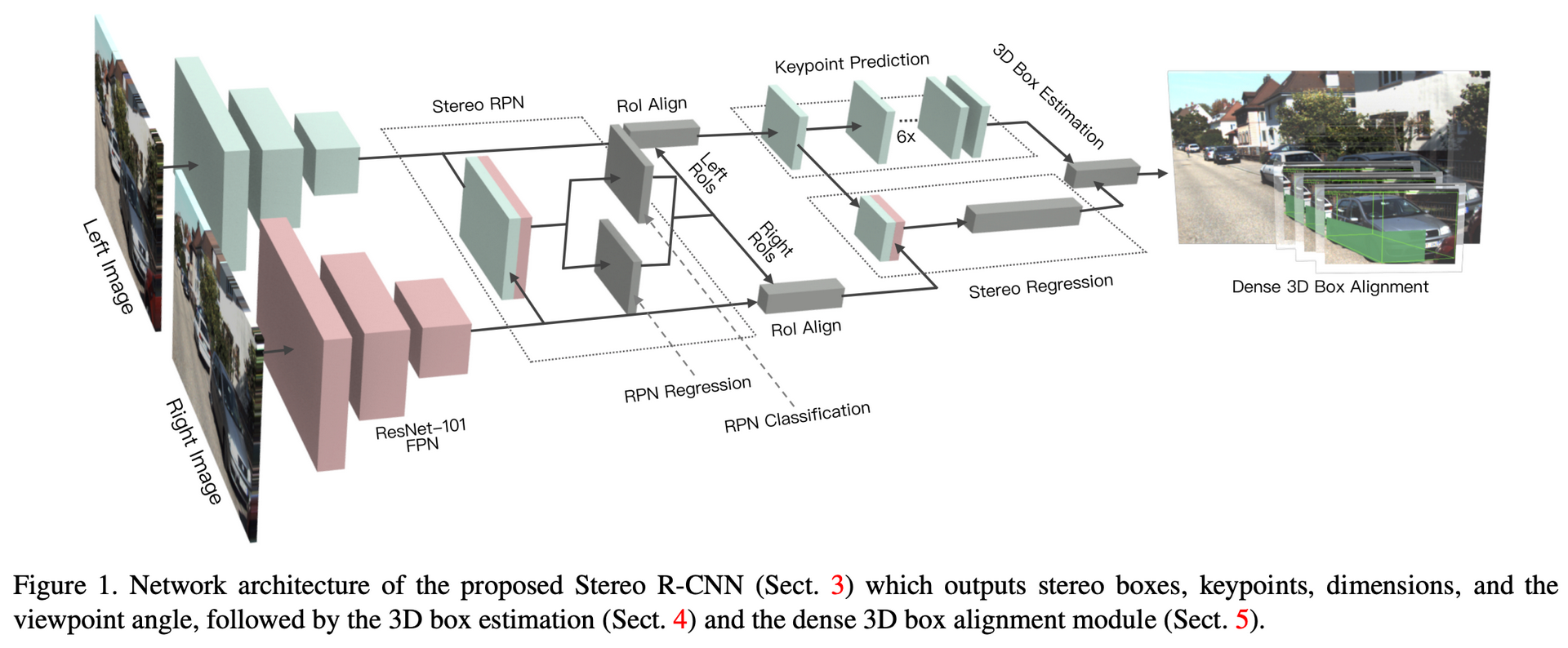
Stereo RCNN extends Faster RCNN, as shown below:
Backbone
The authors use ResNet-101 combined with FPN, with shared weights. This backbone processes the left and right images at the same time, and the results are then merged as the input of Stereo RPN.
Stereo RPN
To make the anchors generated for the left and right boxes correspond to each other, the authors use different GT boxes for objectness classification and box regression, as follows:
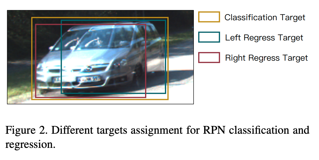
- In the objectness classification stage, the bounding rectangle of the corresponding left and right GT boxes is taken as the union GT. An anchor whose IOU with the union GT is above 0.7 is taken as a positive sample, and below 0.3 as a negative sample. Since this IOU computation only involves the size of the anchor, it is the same for the left and right images.
- In the box regression stage, the respective GT boxes are used to regress the anchor coordinates. The parameters to regress are $[u, w, u', w', v, h]$, where $u$ and $v$ denote the horizontal and vertical coordinates of the center of the 2D box, and $h$ and $w$ denote its length and width. Because the input left and right images are rectified, the vertical coordinates of the left and right images are basically the same, that is, $v$ and $h$ are essentially the same.
Finally NMS is used to take the top 2000 samples for training, and 300 at test time.
Stereo RCNN
As can be seen from the network structure figure above, after Stereo RPN and the regular ROI Align there are two branches, namely Stereo Regression and Keypoint Prediction.
Stereo Regression
After performing ROI Align on the left and right images separately, the results are concatenated and fed into fully connected layers. Here the ROIs are filtered: when the IOU of the left and right ROIs with the GT is both greater than 0.5 the sample is positive, and when it is less than 0.5 but at least 0.1 it is negative. The regression parameters are:
- object class
- bounding box: the same as in stereo rpn
- object dimension: the average size is computed first, then the relative quantity is predicted
- viewpoint angle: $[sin\alpha, cos\alpha]$
Regarding the viewpoint angle, see the figure below:
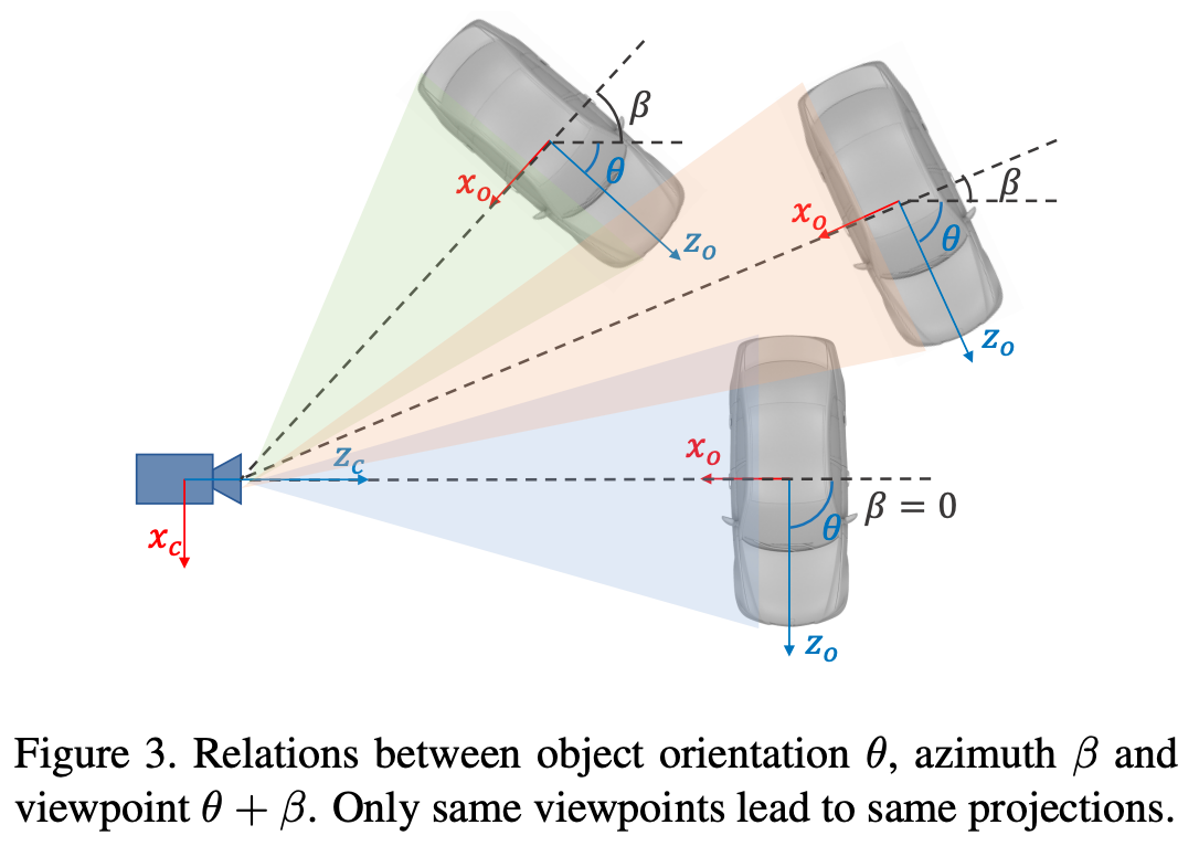
$\theta$ is the orientation angle of the object in the camera coordinate system, and $\beta$ is the azimuth angle of the object relative to the camera center. These three quantities projected onto the camera are basically the same, so to distinguish them better the authors choose to regress the view angle, that is, $\alpha = \theta + \beta$, where $\beta = arctan(-\frac{x}{z})$, and to maintain continuity the final regression parameters are $[sin\alpha, cos\alpha]$.
Keypoint Prediction
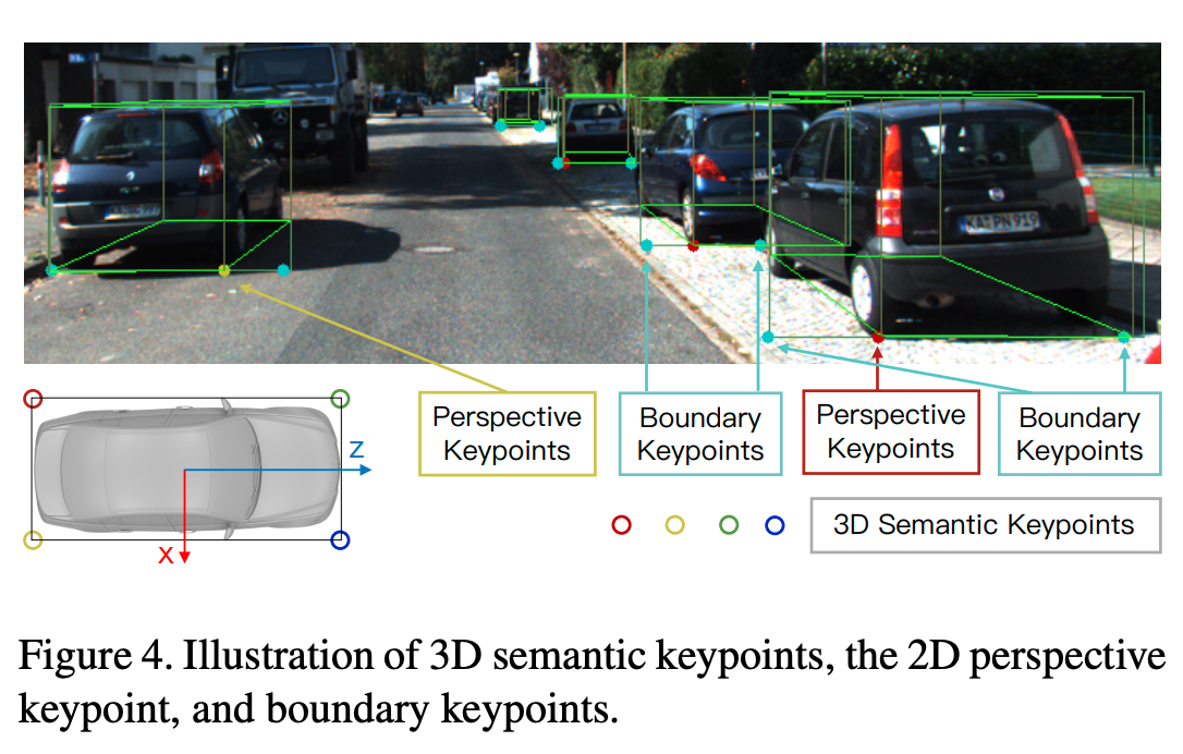
Projecting the four bottom points of the 3D object box onto the image plane reveals that at most one 3D keypoint can be clearly projected inside the box (not on the left or right edge); the authors define this 3D keypoint as the perspective keypoint and only predict it on the left image. This keypoint can effectively constrain the 3D object box. For the concrete implementation details, refer to the original paper.
3D Box Estimation
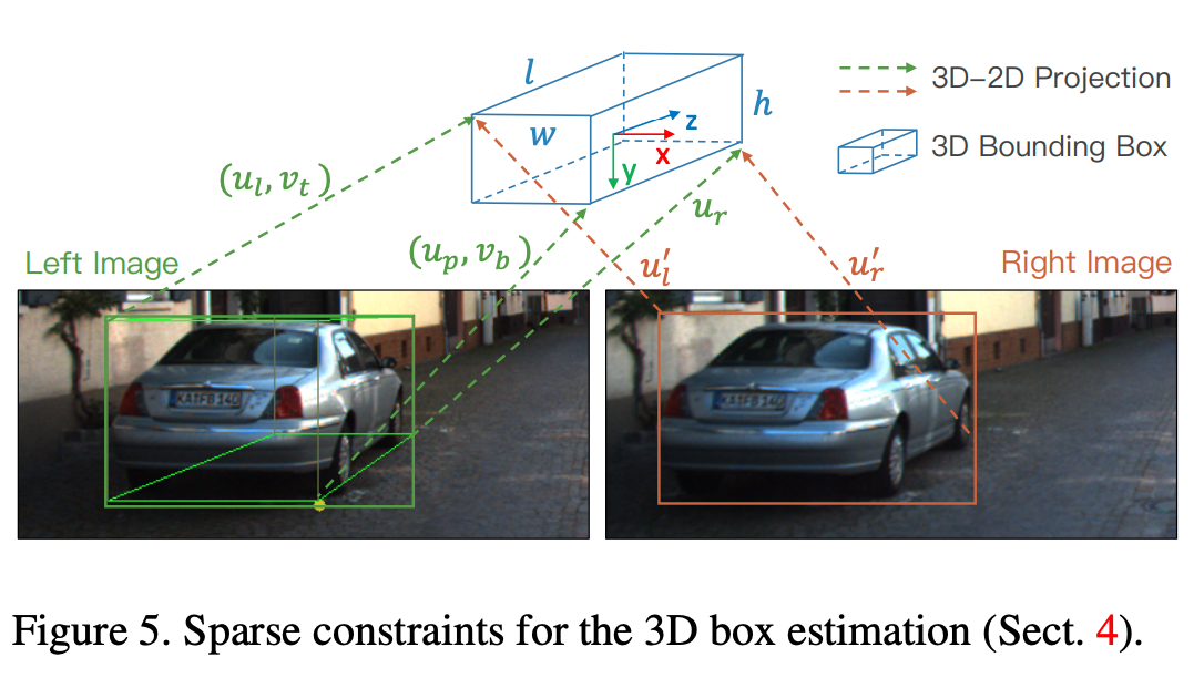
Now we already have the 2D box, the size, the view angle and the perspective keypoint; with these we can obtain a preliminary 3D box: $(x, y, z, \theta)$, that is, the center point and orientation angle of the 3D box. The method used minimizes the error of the projection of the 3D box onto the 2D box and the keypoints.
The input is $\mathbf{z} =\{u_l, v_t, u_r, v_b, u'_l, u'_r, u_p\}$, denoting the coordinates of the top-left and bottom-right corners of the 2D box in the left image, the left and right coordinates in the $u$ direction of the 2D box in the right image, and the coordinates of the perspective keypoint. Equations are established by projecting the object points in the world coordinate system to the object points in image coordinates, for example the projection of the top-left corner:
$$ \begin{bmatrix} u_l \\ v_t \\ 1 \end{bmatrix} = \begin{bmatrix} x \\ y \\ z \end{bmatrix} + \begin{bmatrix} cos\theta & 0 & sin\theta \\ 0 & 1 & 0 \\ -sin\theta & 0 & cos\theta \end{bmatrix} \cdot \begin{bmatrix} -\frac{w}{2} \\ -\frac{h}{2} \\ -\frac{l}{2} \end{bmatrix} $$This gives the equations for $u_l$ and $v_t$. The equations for the other parameters in $\mathbf{z}$ can be derived in the same way (noting the changes of sign), and are then solved with the Gauss-Newton method.
The paper specifically notes that, for convenience of representation, the parameters in $\mathbf{z}$ have already been normalized by the camera intrinsics
Dense 3D Box Alignment
This part refines the accuracy of the 3D box obtained above. The authors define the region within the object range that lies below half of its height and between the left and right edges of the object as the valid region, and optimize over this ROI. The error function is defined as follows:
$$ \begin{aligned} E & = \sum_{i = 0}^Ne_i \\ & = \sum_{i = 0}^N\left \| I_l(u_i, v_i) - I_r(u_i - \frac{b}{z + \Delta z_i}, v_i) \right \| \end{aligned} $$Combined with triangulation, the formula above can be understood as the authors converting the change in object depth into a change in image pixel coordinates, that is, disparity; the formula can in fact be seen as a way of computing a cost volume. Thus, by changing the pixel coordinate values the depth value changes, and the smallest overall pixel difference between the left and right images corresponds to the optimal $z$ value. A coarse-to-fine strategy can be used, for example first searching 50 steps at a precision of 0.5m, then searching 20 times at a precision of 0.05m.
This method can be applied to the post-processing of other stereo 3D detectors. Because the object ROI is a physical constraint, this method avoids the discontinuous, ill-posed problems of depth estimation, and it is robust to illumination, since every pixel contributes to the estimate.
Reference
Stereo R-CNN based 3D Object Detection for Autonomous Driving
paper_reading-Stereo R-CNN based 3D Object Detection for Autonomous Driving